6. Input & Output device
Individual assignment
A-Buzzer
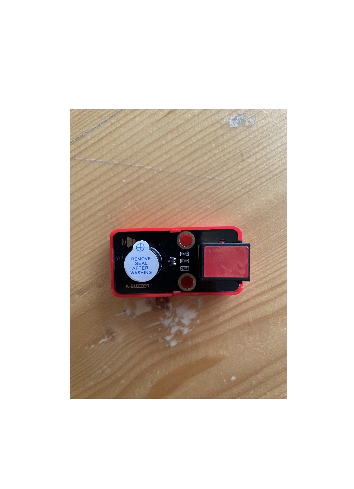
A buzzer is an electronic device that generates sound by converting electrical energy into sound energy. It typically consists of a piezoelectric crystal, which expands and contracts when an alternating current is applied to it, creating sound waves. It can be controlled using a variety of methods, such as using a microcontroller to generate a square wave with the correct frequency, or using a specialized IC. Buzzers are commonly used in a range of applications, including alarms, notifications, and tone generation.
To control a buzzer with an ESP32, connect the buzzer to a digital output pin and write code to manage the pin’s state. The ESP32’s digital output pins can be set to high or low, allowing you to produce a square wave by rapidly toggling a pin between these states at a specific frequency, which causes the buzzer to sound.
C++ Code:
// Define the pin connected to the buzzer
const int buzzerPin = 27;  // Adjust to your actual pin

// Set the times in milliseconds (e.g., 10 seconds ON, 5 seconds OFF)
const unsigned long buzzerOnTime = 500;  // 10 seconds ON
const unsigned long buzzerOffTime = 2000;  // 5 seconds OFF

void setup() {
  // Initialize the buzzer pin as an output
  pinMode(buzzerPin, OUTPUT);
}

void loop() {
  // Turn the buzzer ON for a long time
  digitalWrite(buzzerPin, HIGH);  // Buzzer ON
  delay(buzzerOnTime);  // Keep the buzzer ON for the specified time

  // Turn the buzzer OFF for a long time
  digitalWrite(buzzerPin, LOW);  // Buzzer OFF
  delay(buzzerOffTime);  // Keep the buzzer OFF for the specified time
}
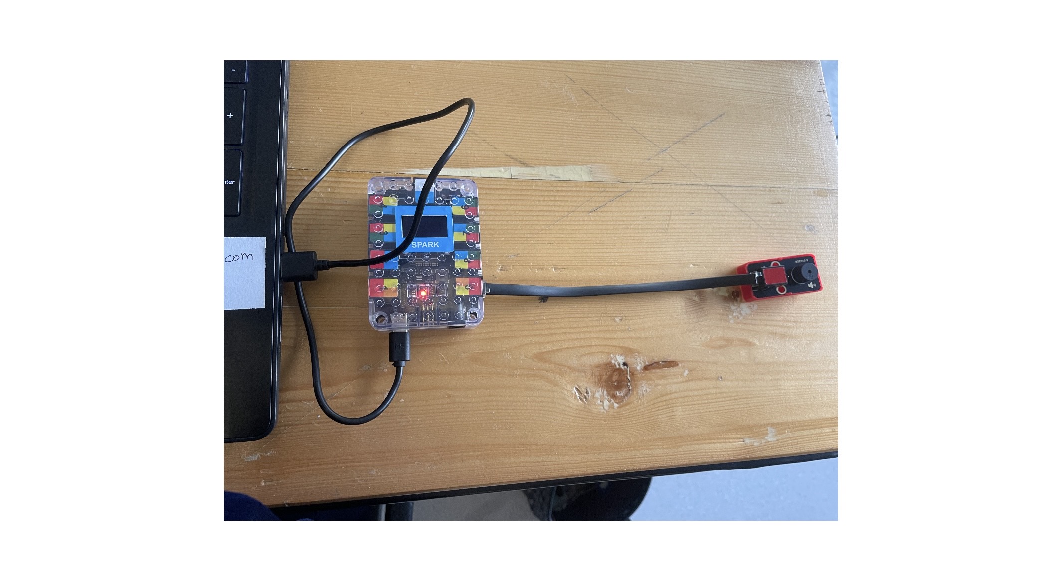
I control a buzzer connected to pin 27 of a microcontroller by turning it on and off in a repeating cycle. I set the buzzer to sound for 0.5 seconds, followed by a silent period of 2 seconds. In the loop function, I continuously activate the buzzer, keeping it on for the specified duration before turning it off and waiting for the off duration, which creates a rhythmic sound pattern.
Result:
130DC fan motor
The 130 DC fan motor is a compact, lightweight motor typically operating at 12 volts. It is known for high efficiency, low power consumption, and durability. Commonly used in cooling systems, ventilation, and automotive applications, it allows for adjustable speed control and is ideal for dissipating heat in electronics and small appliances.
C++ Code:
// Pin definitions
#define ENA 12       // PWM pin to control motor speed
#define IN1 13      // Input 1 for motor direction
#define IN2 14      // Input 2 for motor direction

// Speed settings (0-255)
double motorSpeed = 0;
double minSpeed = 0;
double maxSpeed = 255;
double inc = 10;

void setup() {
  // Set motor control pins as outputs
  pinMode(ENA, OUTPUT);
  pinMode(IN1, OUTPUT);
  pinMode(IN2, OUTPUT);

  // Start serial communication for debugging
  Serial.begin(9600);
  Serial.println("130 DC Fan Motor Control Initialized");
}
void loop() {
    // Fade from low to slightly higher speed
    for (motorSpeed = minSpeed; motorSpeed <= maxSpeed; motorSpeed += inc) {
        controlMotor(motorSpeed, true); // Run forward
        delay(100);
    }

    // Hold at medium-slow speed for 2 seconds
    delay(2000);

    // Gradually reduce speed back to low
    for (motorSpeed = maxSpeed; motorSpeed >= minSpeed; motorSpeed -= inc) {
        controlMotor(motorSpeed, true); // Run forward
        delay(100);
    }

    // Pause motor for 2 seconds
    stopMotor();
    delay(2000);
}

// Function to control the motor
void controlMotor(int speed, bool forward) {
  analogWrite(ENA, speed); // Set motor speed
  if (forward) {
    digitalWrite(IN1, HIGH);
    digitalWrite(IN2, LOW);
  } else {
    digitalWrite(IN1, LOW);
    digitalWrite(IN2, HIGH);
  }
}

// Function to stop the motor
void stopMotor() {
  digitalWrite(IN1, LOW);
  digitalWrite(IN2, LOW);
  analogWrite(ENA, 0); // Ensure PWM is 0
}
This Arduino code regulates a 130DC fan motor using PWM for speed control and two digital pins for direction. It defines three pins and sets them up in the setup() function. In the loop(), the motor speed gradually increases to maximum, holds for a while, then decreases back to zero, with pauses in between.
The controlMotor function sets the speed and direction based on inputs, while the stopMotor function stops the motor. This allows for smooth acceleration, deceleration, and stopping of the motor.
Result:
Potentiometer
A potentiometer is a three-terminal variable resistor used to adjust voltage levels in electronic circuits. It consists of a resistive element and a movable contact (wiper) that changes resistance. Commonly found in volume controls and tuning circuits, it allows users to fine-tune electronic signals by varying the output voltage based on the wiper’s position.
C++ Code:
// Define the pin where the potentiometer is connected
const int potentiometerPin = 4;  // Pin 4 is the analog input pin for the potentiometer

void setup() {
  // Start serial communication at 9600 baud rate
  Serial.begin(9600);
}

void loop() {
  // Read the potentiometer value (0 to 1023)
  int potentiometerValue = analogRead(potentiometerPin);

  // Print the potentiometer value to the serial monitor
  Serial.print("Potentiometer Value: ");
  Serial.println(potentiometerValue);

  // Wait for a short period before reading again
  delay(500);  // Delay for 500 milliseconds
}
This code is designed to read the value from a potentiometer connected to pin 4 of esp32 microcontroller. In the setup function, it initializes serial communication at a baud rate of 9600. Inside the loop function, it continuously reads the analog value from the potentiometer, which ranges from 0 to 1023, and sends this value to the serial monitor for display. It includes a 500-millisecond delay between readings to regulate the output frequency. This setup is useful for monitoring user input in real-time.
Result:
Fan-potentiometer code:
#include <Arduino.h>

// Define the pin connected to the fan's PWM input
const int fanPin = 26;

void setup() {
  // Set the fan pin as an output for PWM control
  pinMode(fanPin, OUTPUT);
  Serial.begin(9600); // Initialize serial communication
}

void loop() {
  // Example: Control fan speed based on a potentiometer reading
  // Replace with your actual sensor input or desired speed control logic

  // Read potentiometer value (replace with your sensor reading)
  int sensorValue = analogRead(39);

  // Map sensor value to PWM duty cycle (0-255)
  int fanSpeed = map(sensorValue, 0, 4095, 0, 255);

  // Set the fan speed using PWM
  analogWrite(fanPin, fanSpeed);

  // Print the fan speed to the serial monitor
  Serial.print("Fan Speed: ");
  Serial.println(fanSpeed);
  Serial.print("Sensor Value: ");
  Serial.print(sensorValue);
  delay(100); // Delay for smoother speed control
}
Result:
Film Pressure
Film pressure input microcontrollers are devices used in film production to monitor and control pressure levels during processes like film processing. They integrate sensors for real-time data, allowing filmmakers to maintain optimal conditions and improve production efficiency, ultimately enhancing the quality of the final product.
C++ Code:
const int ledPin = 2; // GPIO pin connected to the LED
const int sensorPin = 4; // Analog pin connected to the pressure sensor

void setup() {
  // Initialize serial communication
  Serial.begin(115200);

  // Set the LED pin as an output
  pinMode(ledPin, OUTPUT);
}

void loop() {
  // Read the analog value from the sensor
  int sensorValue = analogRead(sensorPin);

  // Map the sensor value to a pressure range (adjust as needed)
  int pressure = map(sensorValue, 0, 4095, 0, 100); // Adjust the range based on your sensor

  // Control the LED based on pressure
  if (pressure > 50) { // Adjust the threshold as needed
    digitalWrite(ledPin, HIGH); // Turn on the LED
  } else {
    digitalWrite(ledPin, LOW); // Turn off the LED
  }

  // Print the sensor value and pressure to the serial monitor
  Serial.print("Sensor Value: ");
  Serial.println(sensorValue);
  Serial.print("Pressure: ");
  Serial.print(pressure);
  Serial.println(" units");

  delay(100); // Delay to slow down the readings
}
Result: