5. Embedded programming
Embedded programming is a specialized area of software development focused on creating software for embedded systems—small computing devices that perform specific tasks within larger systems. These systems are used in various applications, including household appliances, medical devices, automotive systems, and industrial machinery. Developers typically use languages like C and C++ to achieve low-level hardware access, optimizing performance and memory usage. Challenges in embedded programming include limited processing power, memory constraints, and the need for real-time performance, as well as integrating hardware and debugging in unique development environments. Overall, embedded programming is vital for creating efficient and reliable technology in everyday life.
Microcontrollers are compact integrated circuits designed to govern a particular operation in an embedded system. They are essentially miniaturized computers that consist of a processor core, memory, and programmable input/output peripherals. Microcontrollers are used in a wide range of applications, from household appliances to automotive systems, healthcare devices to industrial machinery, and even in robotics and automation.
Group Assignment
We organized ourselves into groups to complete an assignment focused on researching various microcontrollers to broaden our understanding. My group worked specifically with the Arduino WiFi MKR 1010. You can find more details in the link to our group project. click here
Arduino IDE Download
Step 1:
- I visited the Arduino website to download and install the Arduino IDE on my computer.
Step 2:
- I opened the Arduino IDE and installed the ESP32 Board Package:
1. I went to File > Preferences and added the following URL in the “Additional Boards Manager URLs” field: https://raw.githubusercontent.com/espressif/arduino-esp32/gh-pages/package_esp32_index.json
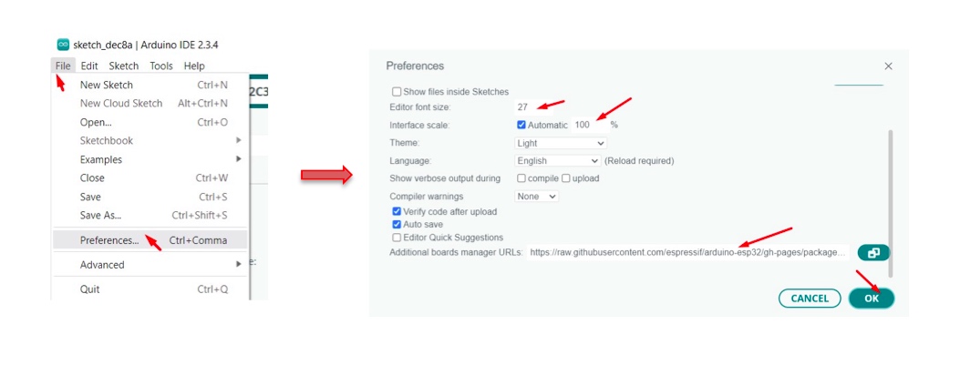
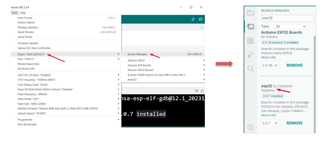
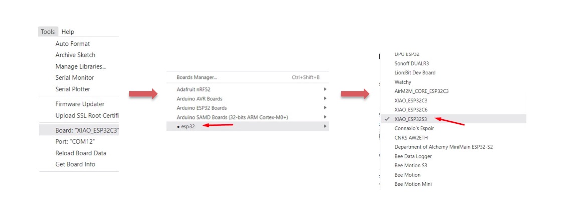
2. I then navigated to Tools > Board > Boards Manager, typed “esp32” in the search box, selected the latest version of the ESP32 package, and clicked Install.
Step 3:
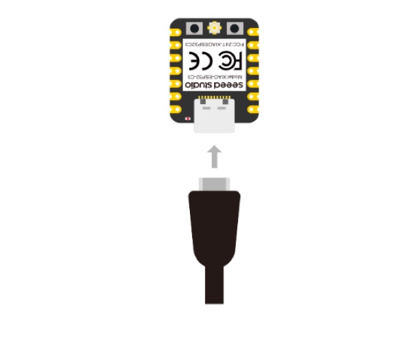
- I connected the XIAO_ESP32S3 microcontroller to the computer using a USB cable.
Step 4:
-
I configured the Arduino IDE:
-
I opened the Arduino IDE and selected the correct board by going to Tools > Board and choosing the XIAO_ESP32S3 model.
-
I then selected the correct port by navigating to Tools > Port and picking the port associated with the connected Arduino, which was named COM12 (ESP32 Family Device) on my computer.
Step 5:
-
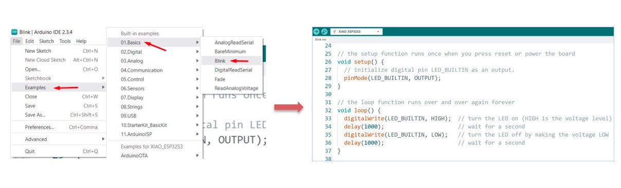
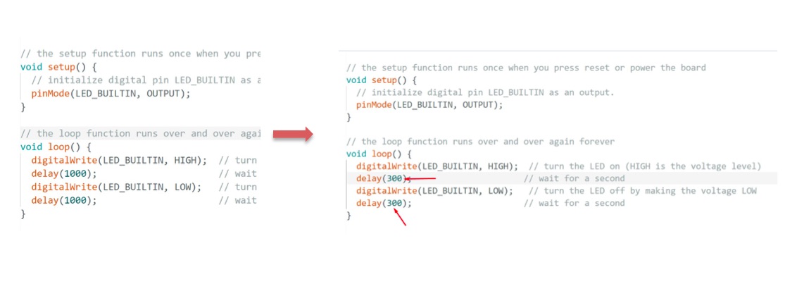
To blink the LED, I clicked on File in the toolbar > Examples > Basics > Blink.
-
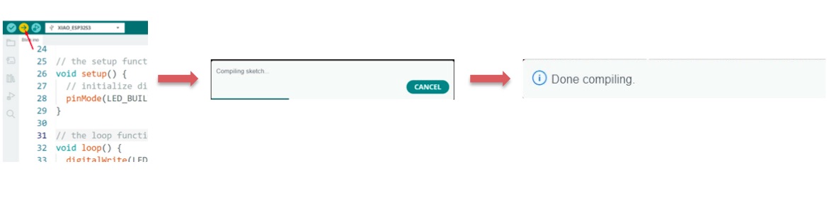
I clicked on Upload, and it started blinking, as shown below.
Result:
- However, I changed the duration of blinking from 1000 to 300, and it blinked faster, as shown below:
Thonny Download
Step 1:
- I visited thonny website to download and install it on my computer.
Step 2:
-
After connecting my microcontroller, I opened Thonny software, went to the toolbar, selected “Run,” and then “Configure Interpreter.”
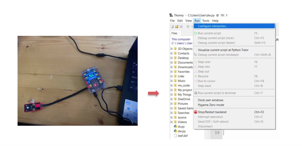
-
I chose “USB Serial @ COM,” clicked “Install,” and selected the correct variant and version of the ESP32 from the dialog box. This step ensured that Thonny was correctly configured with the right MicroPython firmware to enable direct Python code upload to the ESP32 for streamlined application development.

Step 3:
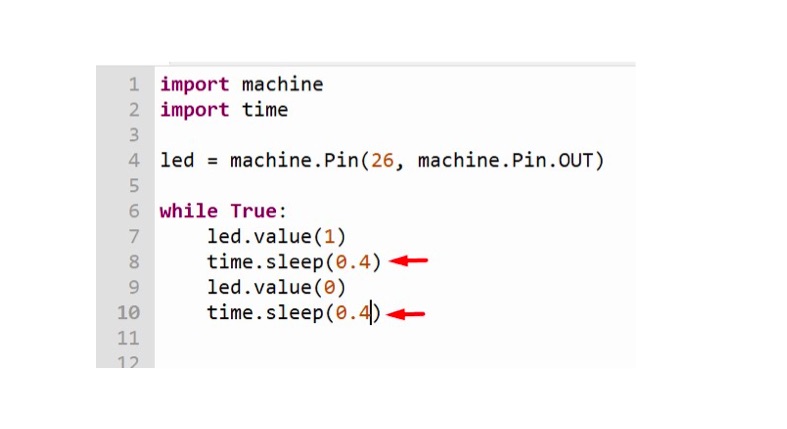
- I added the correct code to blink the led and click on run in toolbar as shown below:
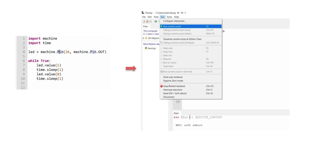
Result:
- I changed the numbers of on and off the led to become faster as shown below:
Result:
Individual Assignment
To conduct various tests on a microcontroller, we were given a worksheet that listed challenges requiring us to identify three different methods for programming the microcontroller using various programming software.
1. Easy mode: Blink your led but have your blink delay periods be randomized values between 1 second and 5 seconds.
C++ code:
int randNumber;
int randDel;

// the setup function runs once when you press reset or power the board
void setup () {
    // initialize digital pin LED_BULLTIN as an output.
    pinMode (LED_BUILTIN, OUTPUT);

    Serial.begin(9600);
    // if analog input pin 0 is unconnected, random analog
    // noise will cause the call to randomSeed() to generate
    // different seed numbers each time the sketch runs.
    // randomSeed() will then shuffle the random function.
    randomSeed(analogRead(0));
}
// the loop function runs over and over again forever
void loop() {
    randNumber = random(1,6); // Random value from 1 to 5
    randDel = random(1,6); // Random value from 1 to 5
    digitalWrite(LED_BUILTIN, HIGH);        // turn the LED on (HIGH is the voltage level)
    delay(randDel*1000);                             // wait for a second
    Serial.println(randDel);
    digitalWrite(LED_BUILTIN, LOW);        // turn the LED on (HIGH is the voltage level)
    Serial.println(randNumber);
    delay(randNumber*1000);
}
- I added this code in Arduino IDE to generates random numbers to control the built-in LED and output to the serial monitor. Then i click on upload.
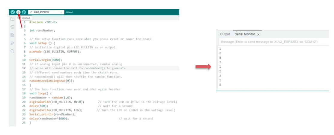
Result:
Python code:
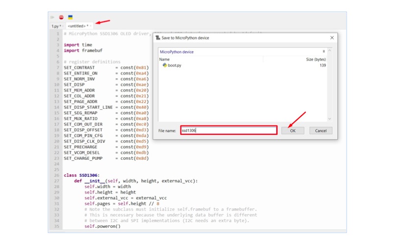
- In thonny software, I created a file named ssd1306.py and saved it directly to the microcontroller device. This file contains the necessary code for interfacing with an SSD1306 OLED display, allowing us to control the display and present various graphics or text.
- I open another file, and added this code. This code manages the built-in LED and an OLED display by utilizing random values.
import machine
import time
import random
import ssd1306

# Initialize the LED pin
led = machine.Pin(26, machine.Pin.OUT)  # Use the built-in LED pin

# Initialize I2C for the OLED display
i2c = machine.I2C(0, scl=machine.Pin(22), sda=machine.Pin(21))  # Adjust pins as necessary
oled = ssd1306.SSD1306_I2C(128, 64, i2c)  # Adjust resolution as necessary

# Seed the random number generator
random.seed(machine.ADC(0).read())  # Use ADC0 for seeding

while True:
    rand_number = random.randint(1, 5)  # Random value from 1 to 5
    rand_del = random.randint(1, 5)      # Random value from 1 to 5

    led.value(1)  # Turn the LED on
    oled.fill(0)  # Clear the display
    oled.text('On for ', 0, 10)  # Display "On for"
    oled.text(str(rand_del) + ' sec', 0, 20)  # Display the random delay
    oled.show()  # Update the display
    time.sleep(rand_del)  # Wait for rand_del seconds

    led.value(0)  # Turn the LED off
    oled.fill(0)  # Clear the display
    oled.text('Off for ', 0, 10)  # Display "Off for"
    oled.text(str(rand_number) + ' sec', 0, 20)  # Display the random duration
    oled.show()  # Update the display
    time.sleep(rand_number)  # Wait for rand_number seconds
- i click on upload code as shown below:

Result:
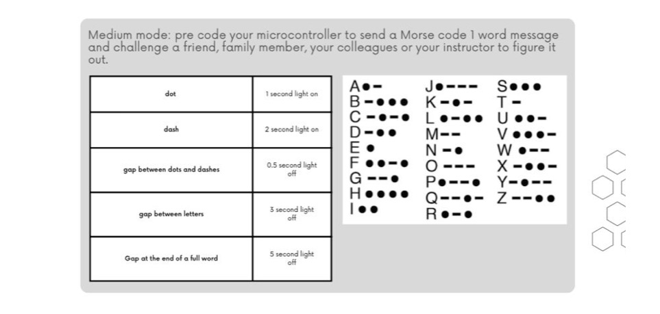
2.
C++ code:
long dot = 1000; // Duration of a dot
long dash = 2000; // Duration of a dash
long dgap = 500; // Duration of a gap between dots and dashes
long lgap = 3000; // Duration of a gap between letters
long wgap = 5000; // Duration of a gap between words

long code[26][4] = {
    {dot, dash, 0, 0}, // A
    {dash, dot, dot, dot}, // B
    {dash, dot, dash, dot}, // C
    {dash, dot, dot, 0}, // D
    {dot, 0, 0, 0}, // E
    {dot, dot, dash, dot}, // F
    {dash, dash, dot, 0}, // G
    {dot, dot, dot, dot}, // H
    {dot, dot, 0, 0}, // I
    {dot, dash, dash, dash}, // J
    {dash, dot, dash, 0}, // K
    {dot, dash, dot, dot}, // L
    {dash, dash, 0, 0}, // M
    {dash, dot, 0, 0}, // N
    {dash, dash, dash, 0}, // O
    {dot, dash, dash, dot}, // P
    {dash, dash, dot, dash}, // Q
    {dot, dash, dot, 0}, // R
    {dot, dot, dot, 0}, // S
    {dash, 0, 0, 0}, // T
    {dot, dot, dash, 0}, // U
    {dot, dot, dot, dash}, // V
    {dot, dash, dash, 0}, // W
    {dash, dot, dot, dash}, // X
    {dash, dot, dash, dash}, // Y
    {dash, dash, dot, dot} // Z
};

void setup() {
    pinMode(LED_BUILTIN, OUTPUT); // Use built-in LED for Morse code
    Serial.begin(9600); // Start serial communication at 9600 baud
    Serial.println("Enter a word to send in Morse code:");
}

void loop() {
    if (Serial.available() > 0) {
        String message = Serial.readStringUntil('\n'); // Read input until newline
        message.toUpperCase(); // Convert to uppercase
        sendMorse(message); // Send the message in Morse code
        Serial.println("Enter another word to send in Morse code:");
    }
}

void sendMorse(String message) {
    for (int i = 0; i < message.length(); i++) {
        char letter = message[i];
        if (letter >= 'A' && letter <= 'Z') {
            int index = letter - 'A';
            for (int j = 0; j < 4; j++) {
                if (code[index][j] == 0) break; // End of letter
                digitalWrite(LED_BUILTIN, HIGH);
                delay(dgap);
                digitalWrite(LED_BUILTIN, LOW);
                delay(code[index][j]);
            }
            delay(lgap); // Gap between letters
        } else if (letter == ' ') {
            delay(wgap); // Gap between words
        }
    }
}
- I opened the Arduino IDE software and uploaded the code to the correct board and port. Upon successful upload, I observed an output box that allowed me to input a word to be translated into Morse code.
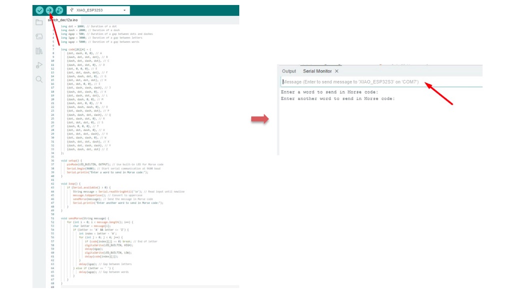
Result:
3. Hard mode: you select the duration of the light being on and off while the program is running by entering it in the serial monitor. Write a code that takes the data from the serial monitor and delays by that amount of time
C++ code:
void setup() {
  // Initialize digital pin LED_BUILTIN as an output
  pinMode(LED_BUILTIN, OUTPUT);

  // Start serial communication
  Serial.begin(9600);
}

// Variable to store the user-defined delay
int delayTime = 1; // Default delay time (1 second)

void loop() {
  // Check if there is input from the Serial Monitor
  if (Serial.available() > 0) {
    // Read the input as a string
    String input = Serial.readString();

    // Convert the input string to an integer
    int newDelayTime = input.toInt();

    // Validate the input
    if (newDelayTime > 0) {
      delayTime = newDelayTime; // Update the delay time
    }
  }

  // Blink the LED
  digitalWrite(LED_BUILTIN, HIGH); // Turn the LED on
  delay(delayTime*100);               // Wait for the specified delay time
  digitalWrite(LED_BUILTIN, LOW); // Turn the LED off
  delay(delayTime*1000);               // Wait for the specified delay time
}
- i added the code and selected the right board and port then click on upload.
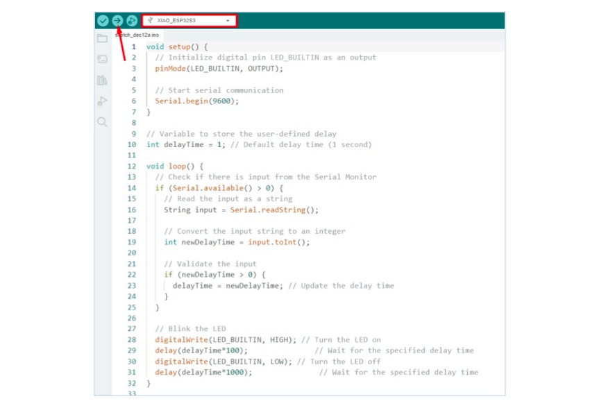
- The code presents an input box where i can enter a number of seconds, and the LED will turn on and off accordingly.
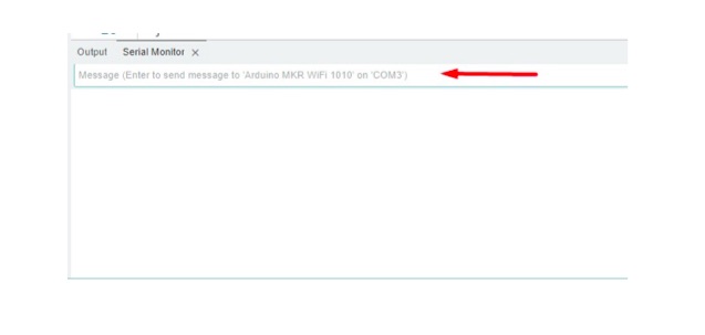
Result:
-
For example, if i enter “1”, the LED will be ON for 1 seconds and then OFF for 1 seconds.
-
If i enter “8”, the LED will be ON for 8 seconds and then OFF for 8 seconds.
Python code:
import machine
import time
import ssd1306
import _thread

# Initialize the LED pin
led = machine.Pin(26, machine.Pin.OUT)  # Use the built-in LED pin (adjust pin number as necessary)

# Initialize I2C for the OLED display
i2c = machine.I2C(0, scl=machine.Pin(22), sda=machine.Pin(21))  # Adjust pins as necessary
oled = ssd1306.SSD1306_I2C(128, 64, i2c)  # Adjust resolution as necessary

# Variable to store the user-defined delay
delay_time = 1  # Default delay time (1 second)

# Function to prompt for user input
def prompt_for_delay():
    global delay_time
    while True:
        print("Enter new delay time in seconds (or press Enter to keep current):")
        input_line = input().strip()  # Use input() to read from the console
        if input_line:
            try:
                new_delay_time = int(input_line)
                if new_delay_time > 0:
                    delay_time = new_delay_time  # Update the delay time
            except ValueError:
                pass  # Ignore invalid input silently

# Start the input thread
_thread.start_new_thread(prompt_for_delay, ())

# Main loop
while True:
    # Turn the LED on
    led.value(1)
    oled.fill(0)  # Clear the display
    oled.text("LED ON", 0, 0)
    oled.text(f"Duration: {delay_time:.1f} sec", 0, 10)  # Display ON duration
    oled.show()
    time.sleep(delay_time)  # Wait for the specified ON duration

    # Turn the LED off
    led.value(0)
    oled.fill(0)  # Clear the display
    oled.text("LED OFF", 0, 0)
    oled.text(f"Duration: {delay_time:.1f} sec", 0, 10)  # Display OFF duration
    oled.show()
    time.sleep(delay_time)  # Wait for the specified OFF duration
- I uploaded the code as shown below:
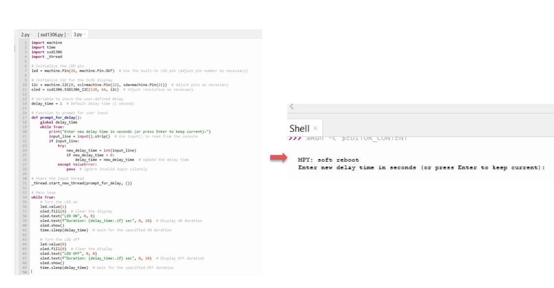
Results:
-
When I randomly selected the number 7, the LED turned off for 7 seconds, as demonstrated below:
-
When I randomly selected the number 1, the LED turned off for 1 second, as shown below: