4. 3D printing and scanning
3D printing, or additive manufacturing, creates three-dimensional objects layer by layer from digital files. It uses materials like plastics and metals and is widely applied in rapid prototyping, healthcare (custom implants), aerospace (lightweight components), and consumer products (customized items). Benefits include product customization, reduced waste, and the ability to create complex designs, though challenges such as material limitations, quality control, and regulatory issues exist. Future advancements are expected to enhance its applications and efficiency, transforming manufacturing and design practices. This week, we will explore two 3D printers: the Ultimaker 2+ and the Creality K1, and we will examine their distinct features.
Group Assignment
We will split into two groups to test a design on two different 3D printers. This method will enable us to effectively compare the results and performance of each printer. For more information, please visit our website.
Individual Assignment
Creating a 3D Model for Printing and Utilizing Scanning Techniques
Print a 3D keychain model
By using K1 creality printer:
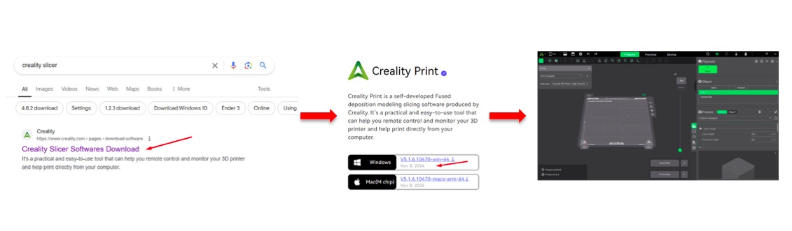
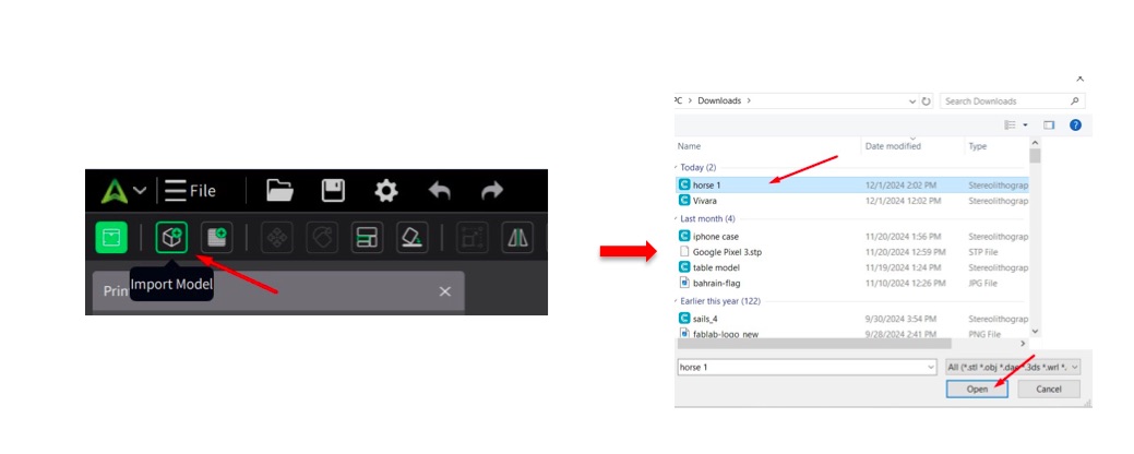
- Download Creality Slicer: I downloaded the Creality Slicer software on my laptop by following the steps shown below.
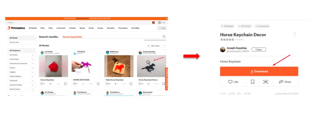
- Select a 3D Model: I picked a design from the Printables website. After making my selection, I clicked on the “Download” button to save the file.
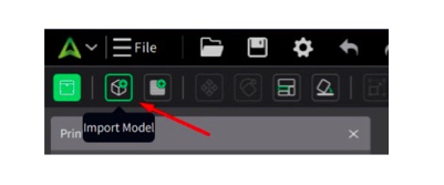
- Import the Model: I opened Creality Slicer, clicked on “Import Model,” and selected the downloaded file.
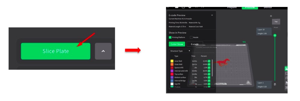
- Slice the Model: I clicked on “Slice Plate” to convert the 3D model into layers, generating the G-code needed for printing.
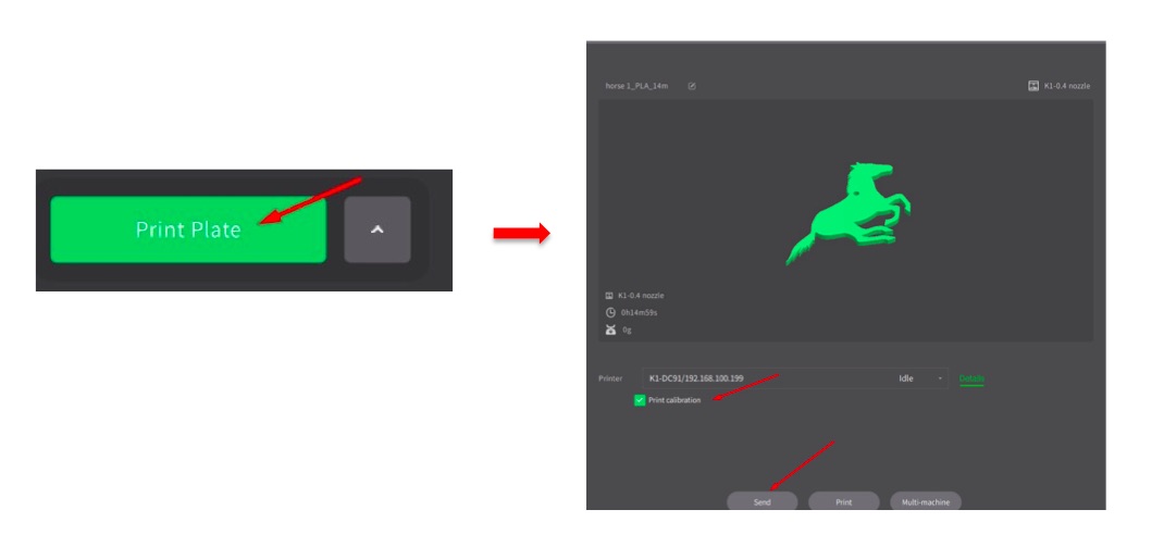
- Send to Printer: I clicked on “Send,” chose the Creality K1 machine.
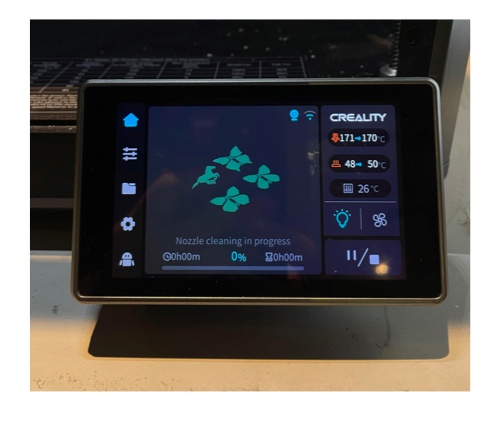
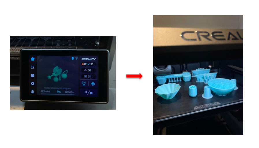
- It started cleaning then print process:
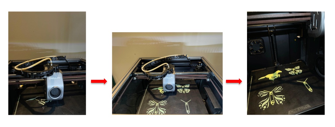
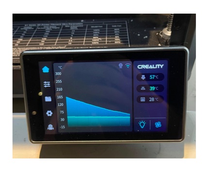
- Cool Down Process: After printing, the fan activated to cool the model down to 40°C.
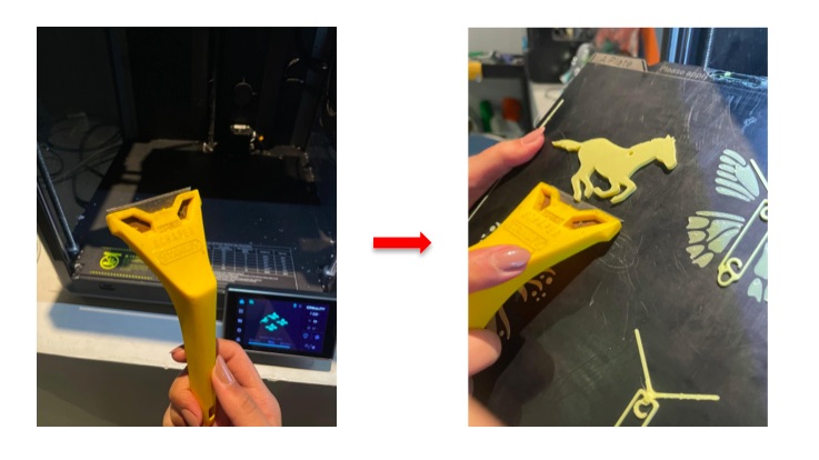
- Remove the Model: Once cooled, I used a scraper to carefully remove my model from the printing plate.
click here to download the file
Design 3D barbell model
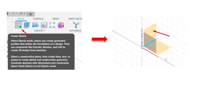
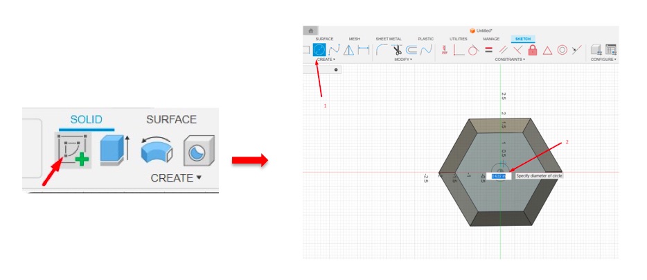
- I opened Fusion 360 and clicked on “Create Sketch.”
- I chose a plane for the sketch.
-
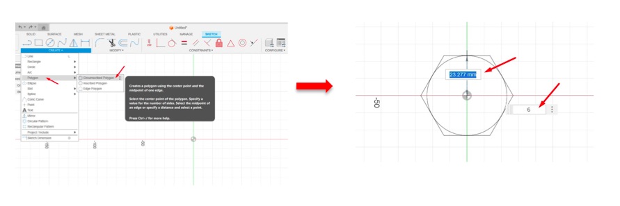
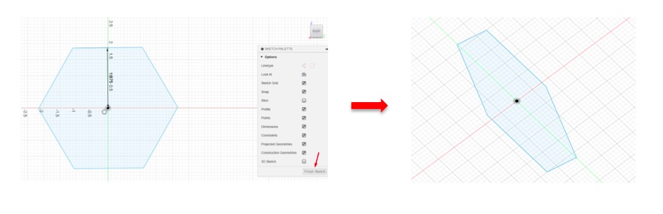
I clicked on “Create,” then selected “Polygon,” and chose “Circumscribed Polygon.” I dragged the polygon to the plane and adjusted its size.
-
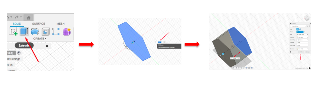
I selected the polygon shape and clicked on “Extrude,” specifying a distance for the extrusion.
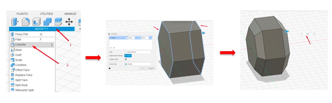
- I clicked on “Modify,” then chose “Chamfer,” selected the edges, and specified an equal distance.
-
I created a new sketch and clicked on “Circle,” drawing a circle with a specific diameter. After creating the circle, I clicked on “Finish Sketch.”
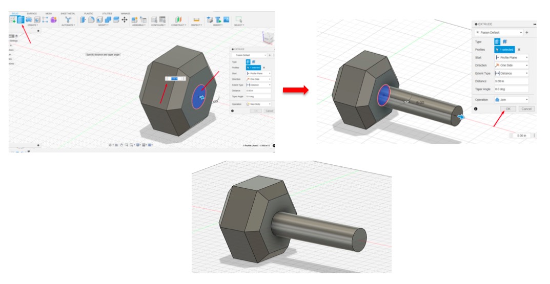
-
I selected the circle and clicked on “Extrude,” setting the distance to 5 inches.
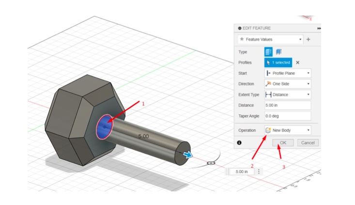
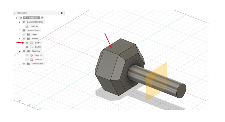
- I clicked on “Edit Feature,” selected the circle, chose “New Body,” and clicked “OK.”
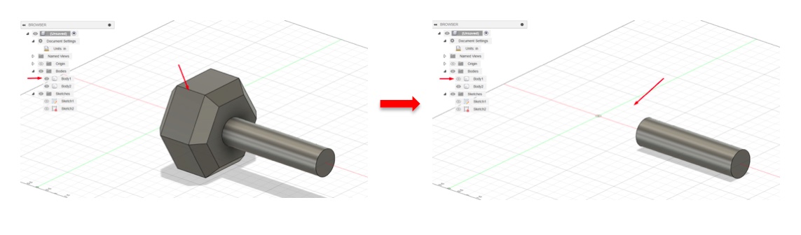
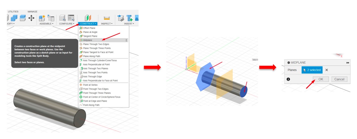
- I went to the browser toolbar and clicked on the eye icon next to “Body1” to make it transparent for adjustments.
- I clicked on “Construct” in the toolbar and chose “Midplane,” then selected two planes and clicked “OK.”
- Next, I clicked on the closed eye icon to return my “Shape1” to view.
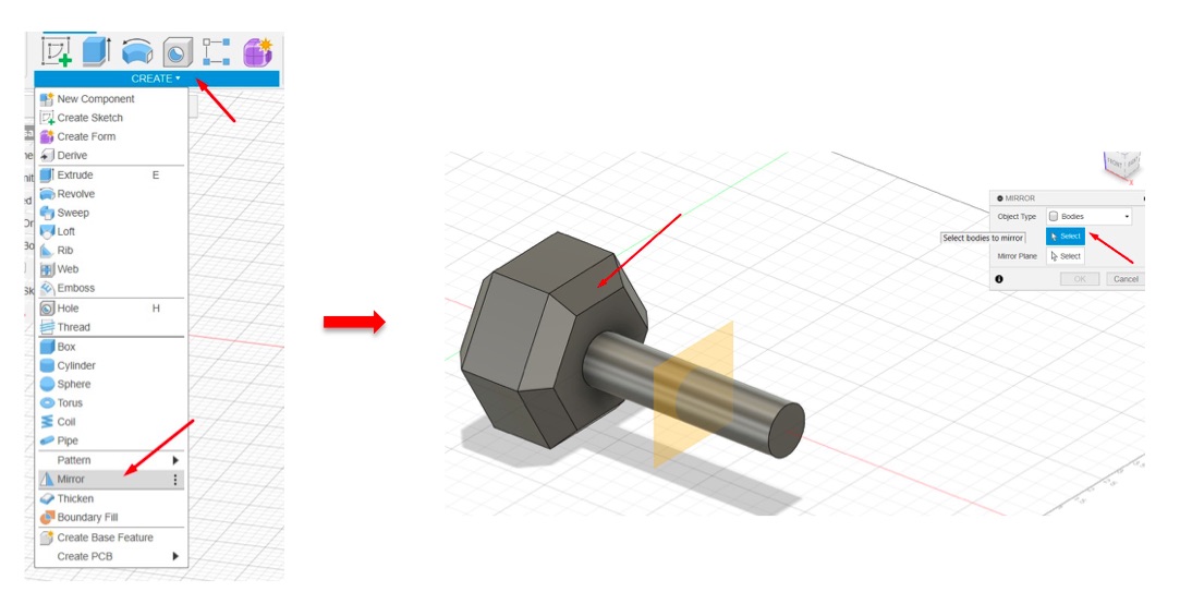
- I clicked on “Create” in the toolbar, then clicked on “Mirror,” selected the object, and specified the mirror plane as shown in the images below.
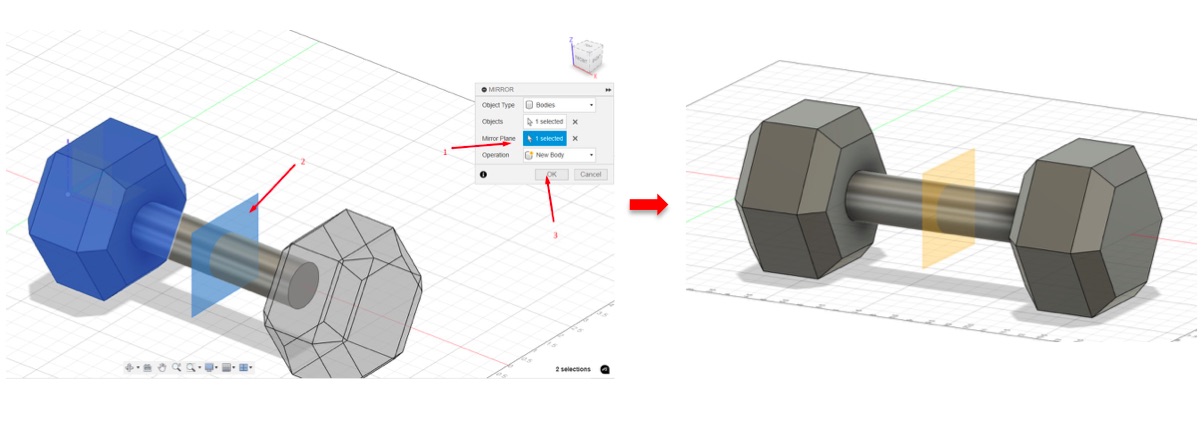
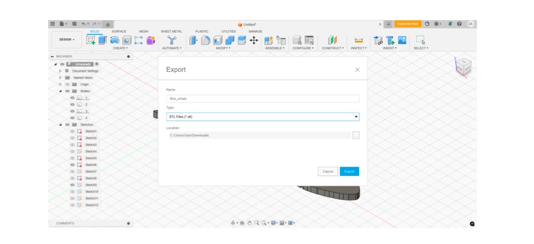
- After that, I checked the final result, went to “File” in the toolbar, and clicked on “Export,” saving the file in STL format.
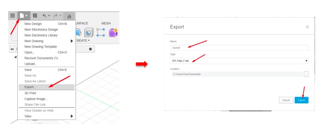
click here to download the file
Design 3D Kettle Bell Model
-
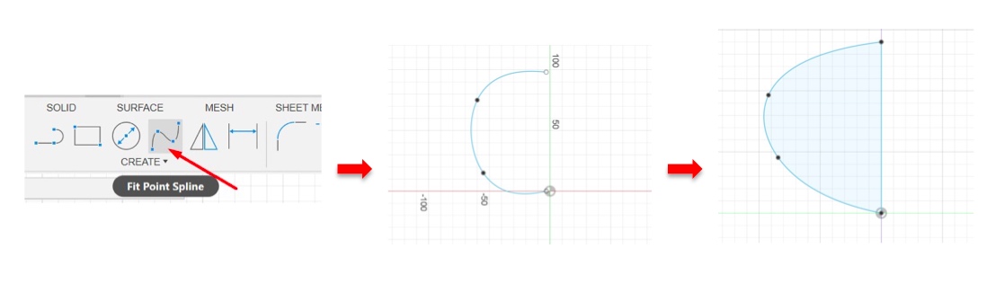
I created a new project and clicked on “Create Sketch,” choosing “Fit Point Spline” to draw a half circle as shown below.
-
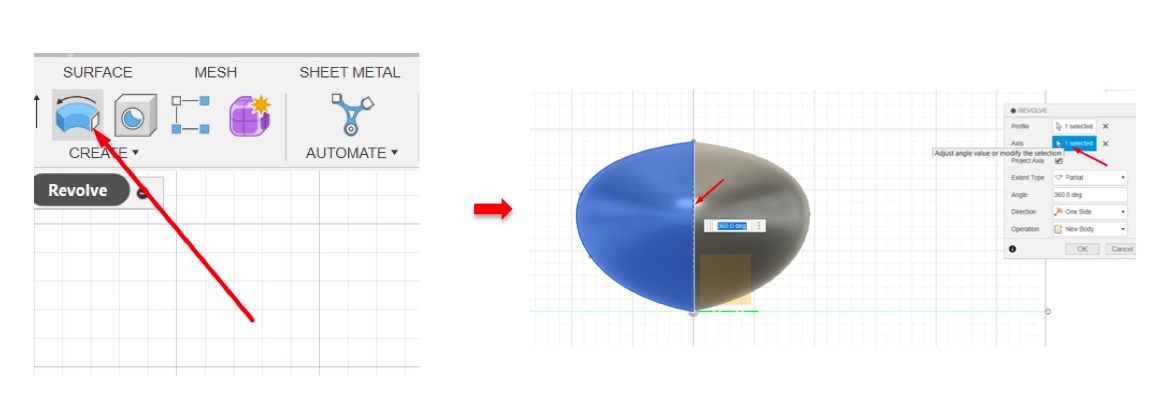
I clicked on “Revolve” in the toolbar and selected the axis to create the other half.
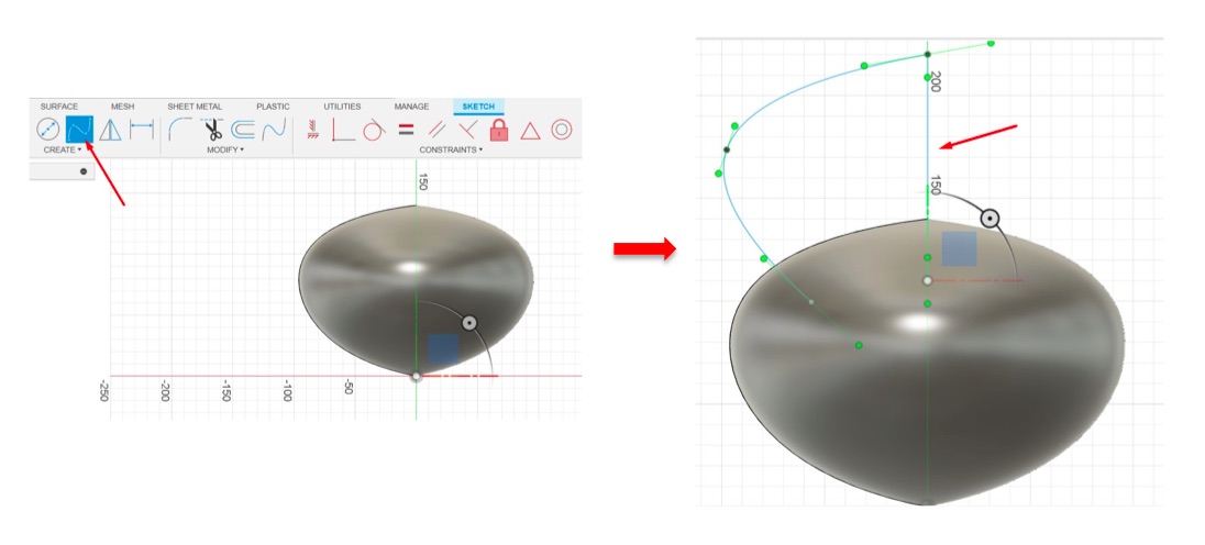
- I created a new sketch, clicked on “Fit Point Spline,” and drew another shape as shown below.
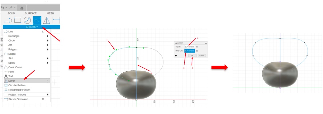
- After that, I clicked on “Create,” chose “Mirror,” selected the object and the mirror line, then clicked “OK.”
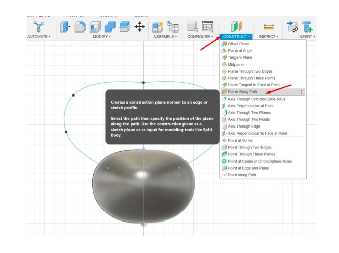
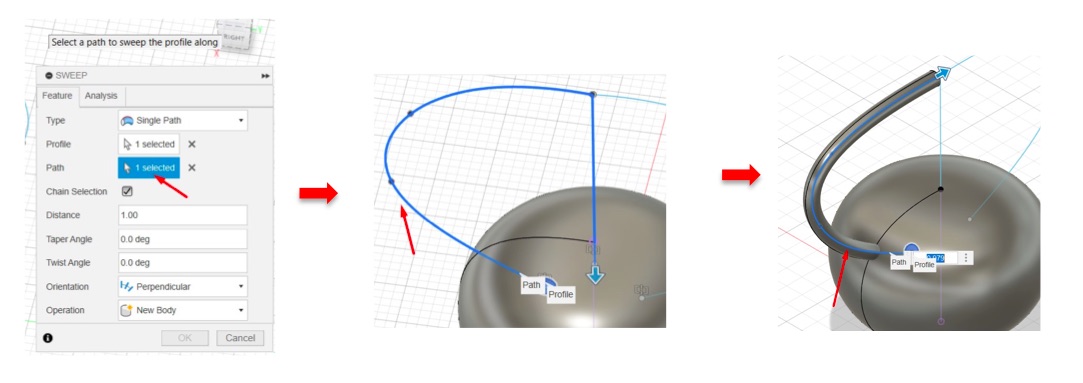
- I clicked on “Construct” in the toolbar and chose “Plane Along Path.”
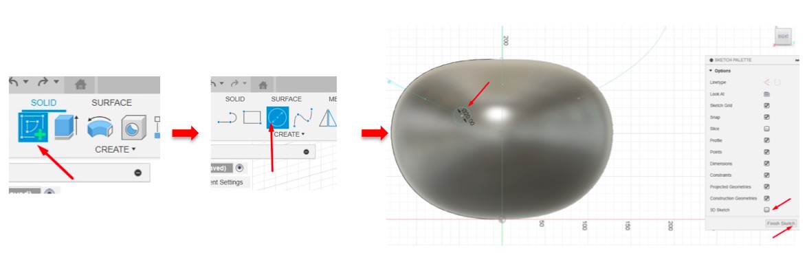
- I then created a sketch, selected a plane face, and chose the circle shape, specifying the diameter. I made sure that the 3D sketch was not selected in the sketch palette, then clicked “OK.”
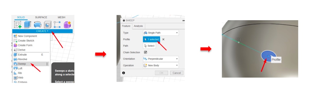
- I clicked on “Create,” then selected “Sweep,” and selected the circle. I chose the desired path, changed it to “New Body,” and clicked “OK.”
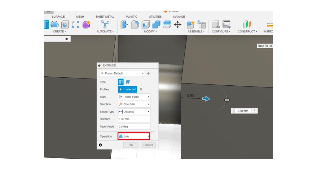
-
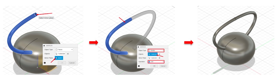
I selected the shape, clicked on “Create,” then chose “Mirror,” selecting the mirror plane and choosing “Join” to combine them together.
-
After that, I went to “File” in the toolbar, and clicked on “Export,” saving the file in STL format.
click here to download the file
Printing on the Creality K1 Machine
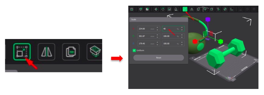
- I opened the Creality Slicer software and imported the barbell and kettlebell models.
- I clicked on “Scale” and adjusted their sizes on the plate.
- I clicked on the support shape in the toolbar and ensured that “Enable Support” was ticked, then clicked on “Slice Plate” as shown below.
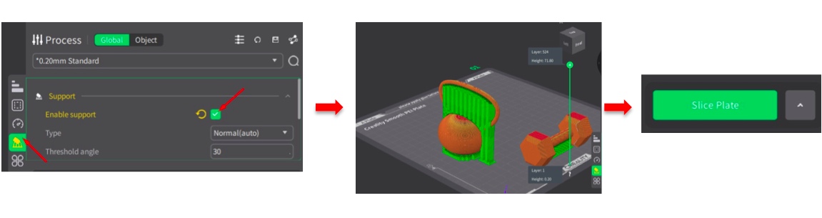
-
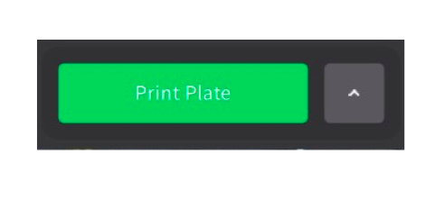
Together with my classmates, we organized our designs on the plate for concurrent printing and then pressed the print button to begin the process.
-
It starts the printing process as demonstrated below:
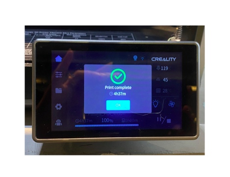
- It completes the printing stage and it takes four hour as shown below:
-
We use a scraper to remove any unwanted parts and the support material.
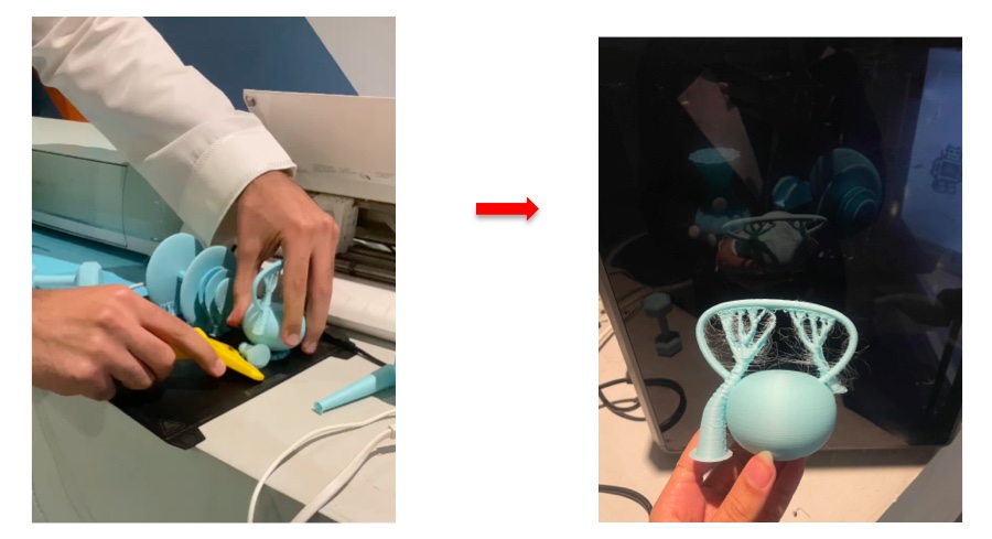
-
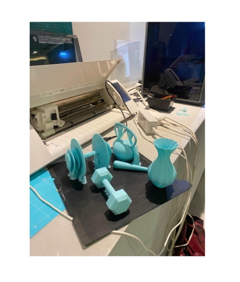
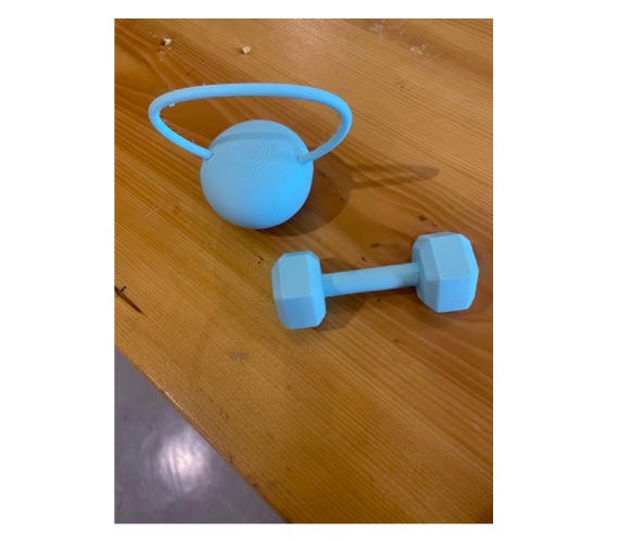
We present the final result as shown below.
Scanning
3D scanning is a technique that captures the physical dimensions and appearance of an object, creating a digital representation that can be manipulated and analyzed in a computer environment. This process typically employs various technologies, such as laser scanning, structured light, or photogrammetry, to produce detailed point clouds or mesh models of the scanned object. The resulting digital file can be used for a wide range of applications, including reverse engineering, quality control, product design, and digital archiving. By enabling the precise capture of intricate details and textures, 3D scanning facilitates innovation in industries such as manufacturing, art, heritage preservation, and medicine, allowing for improved accuracy and efficiency in design and analysis processes.
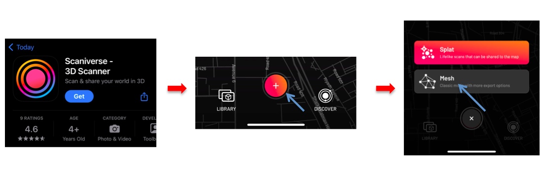
Scaniverse
Scanivers is a software platform that enables users to efficiently manage and process 3D scans and related data.
Steps:
- I opened the Scaniverse app and selected the mesh option.
 - I started scanning the structure, moving my device around to capture all angles.
- After completing the scan, I edited the mesh using the app’s tools.
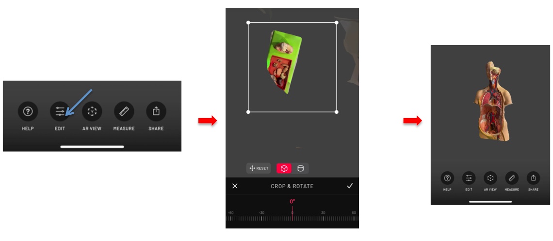
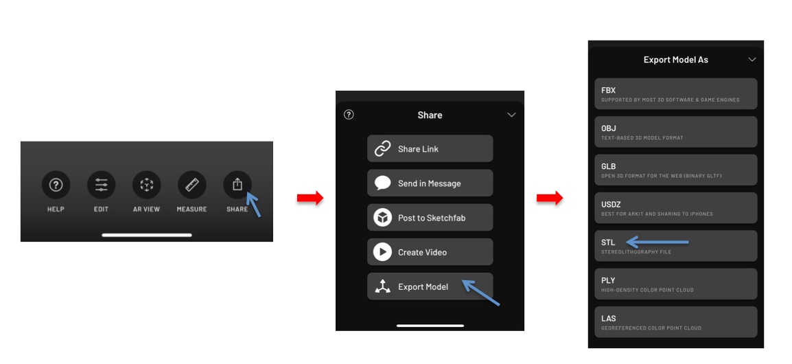
- Finally, I exported the edited model in STL format.
 Click here to download
Scanect
Scanect is a powerful software tool used for 3D scanning and reconstruction. Using a compatible camera, it allows you to create 3D models from physical objects.
Steps:
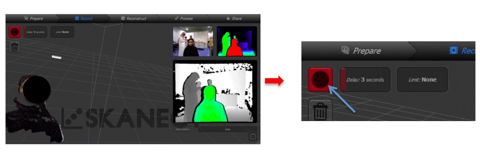
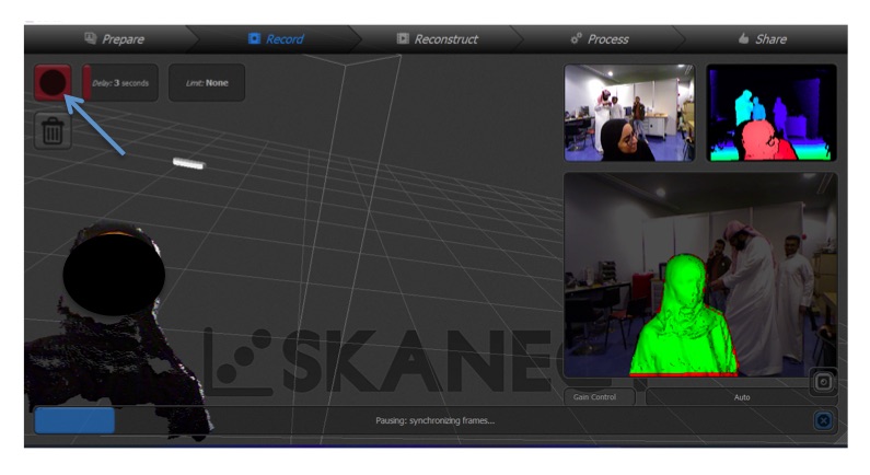
- I opened Scanect and positioned myself within the sensor’s camera field of view.
- My friend started the scan by pressing the designated button as shown below, while I moved slowly and steadily to capture all the necessary angles.
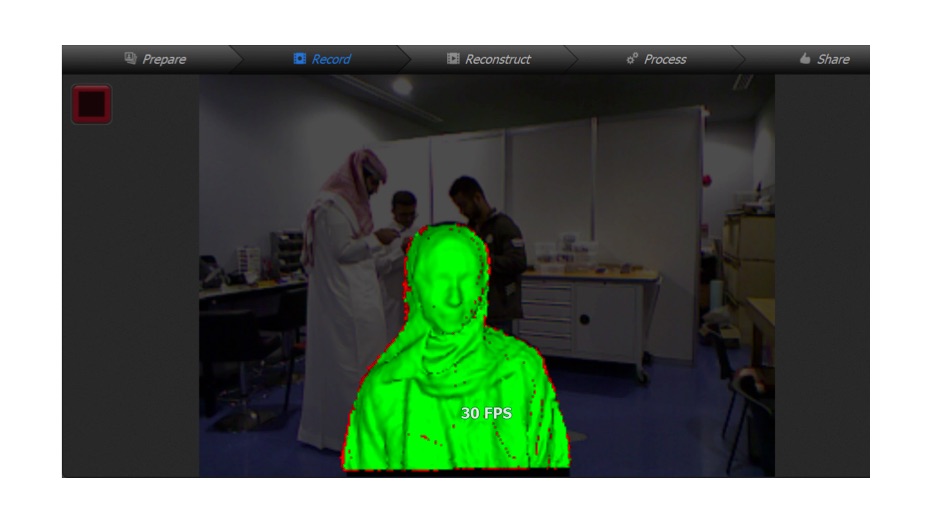
- My friend stopped the scan by pressing the button as shown below.
- I accessed the process button on the toolbar and clicked on simplify to reduce the number of faces.

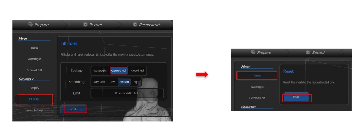
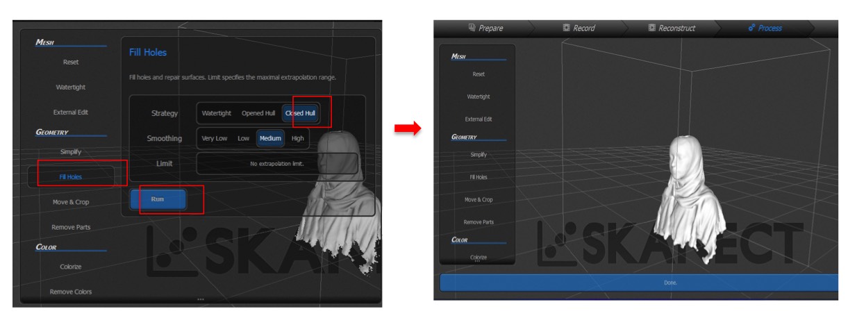
- I clicked on fill holes and compared the open and closed hull options, resetting each step to choose the other option again, before selecting the best one, which was the closed hull, and then clicked on run.
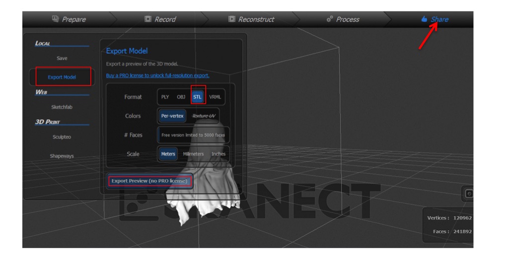
- Finally, I clicked on share in the toolbar, exported the model, chose the STL format, and saved it.
click here to download the file
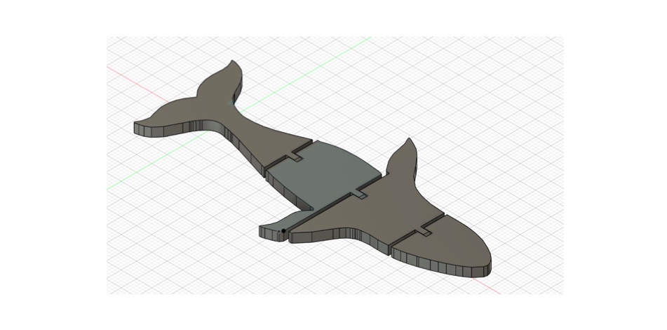
Design a flexi whale model in fusion 360
By following this tutorial :
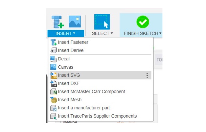
- I opened Fusion 360 and imported the whale image in SVG format.
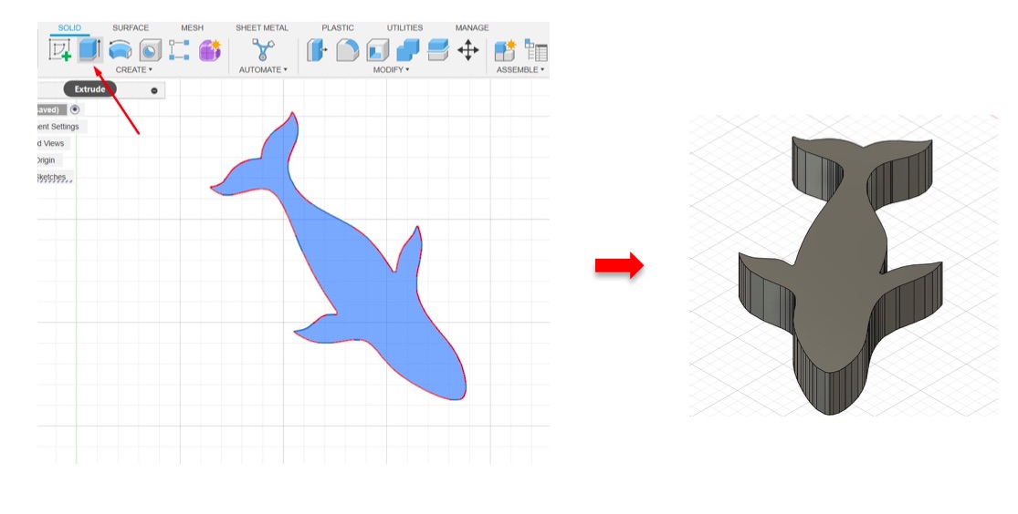
- I extruded the sketch to add depth to the shape.
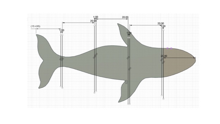
- I created horizontal lines on the surface to segment the model and adjusted them for appropriate spacing.
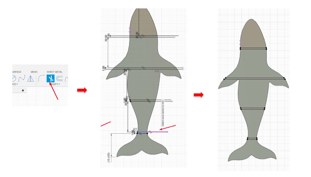
- Then, I trimmed the excess unwanted lines.
- I used the extrude tool to cut through the model, creating individual segments.
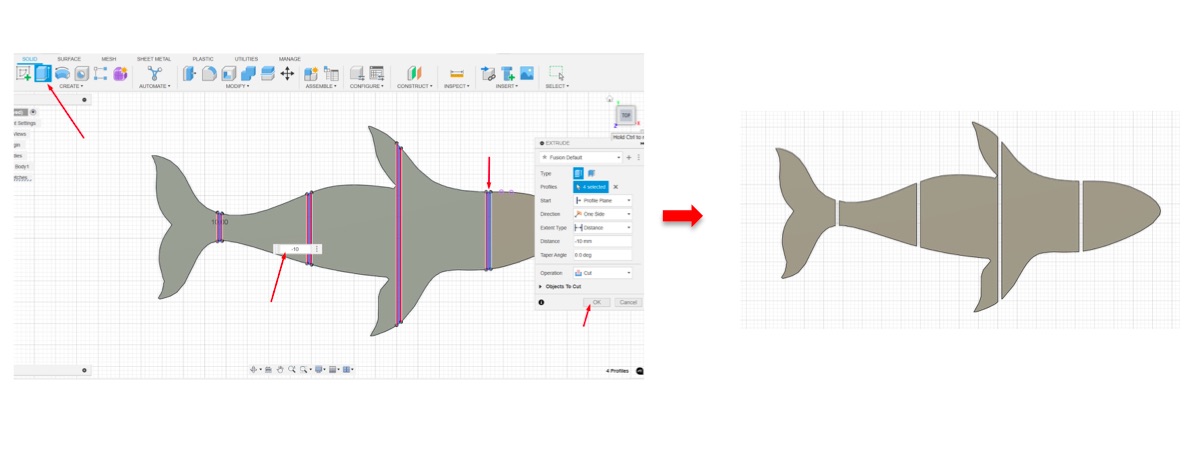
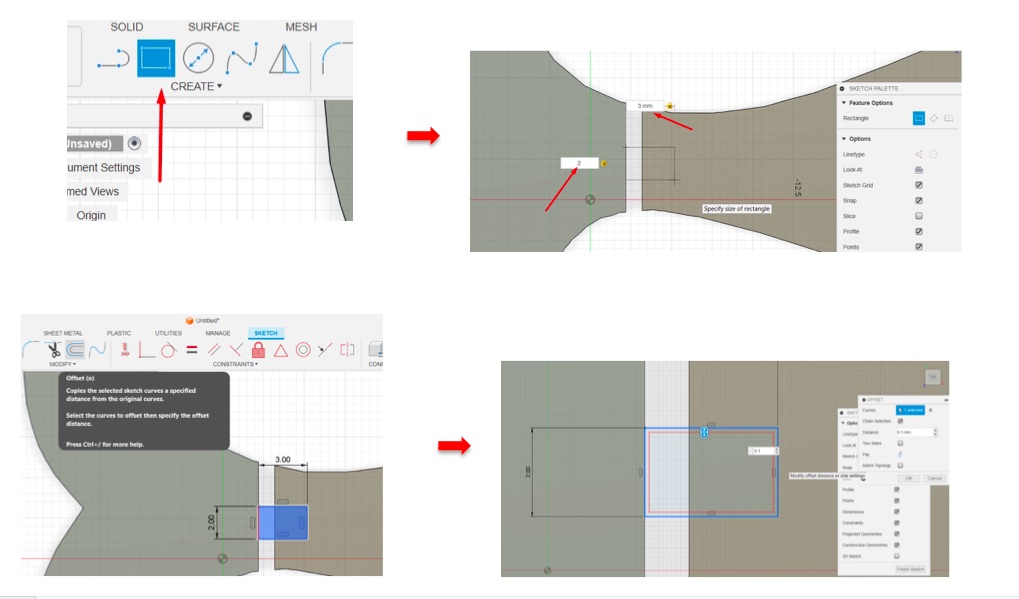
- I created rectangles of a specific size, copied them to all segments, and used the offset tool and modify the distance.
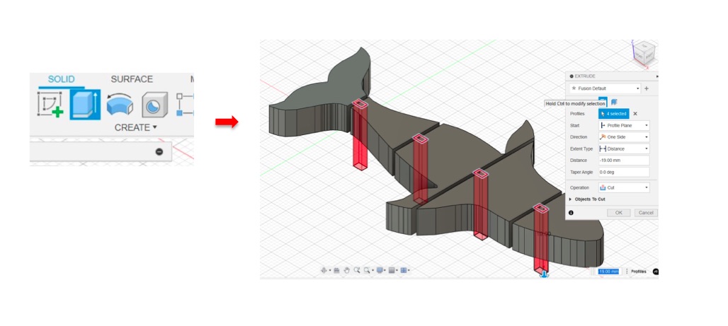
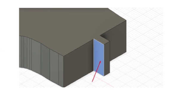
- I extruded all rectangles, ensuring to use the cut operation as shown below.
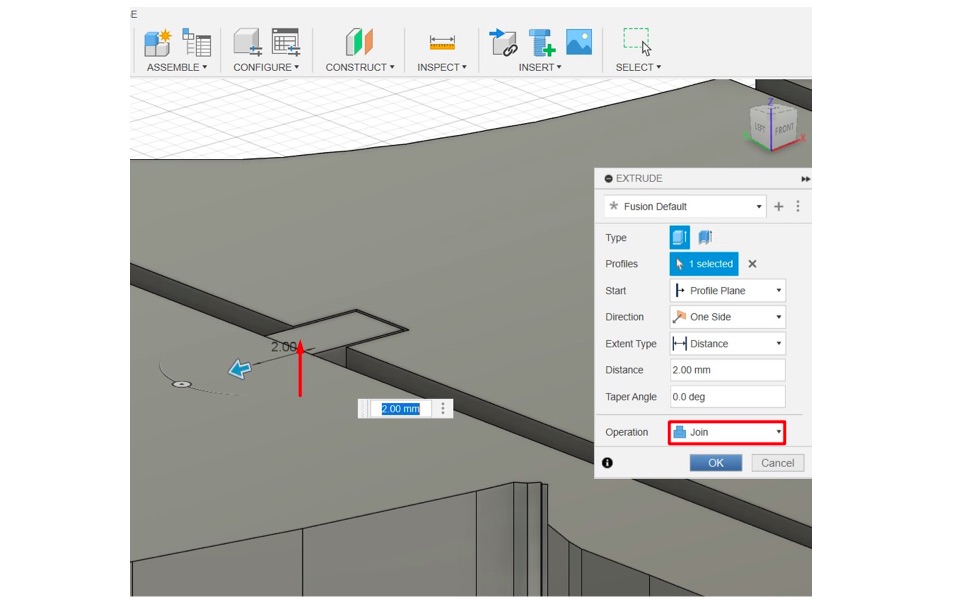
- Then, I extruded the rectangles toward the adjacent segments using the join option.
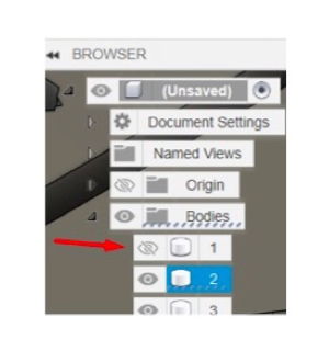
- I removed the first segment by closing the eye of body 1 to make it transparent.
-
Next, I used this face to draw a line and then created three circles, adjusting their sizes.
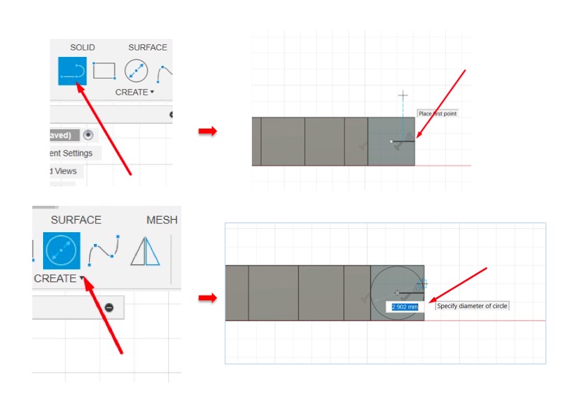
-
I selected all these parts to apply the extrude cut option as shown below.
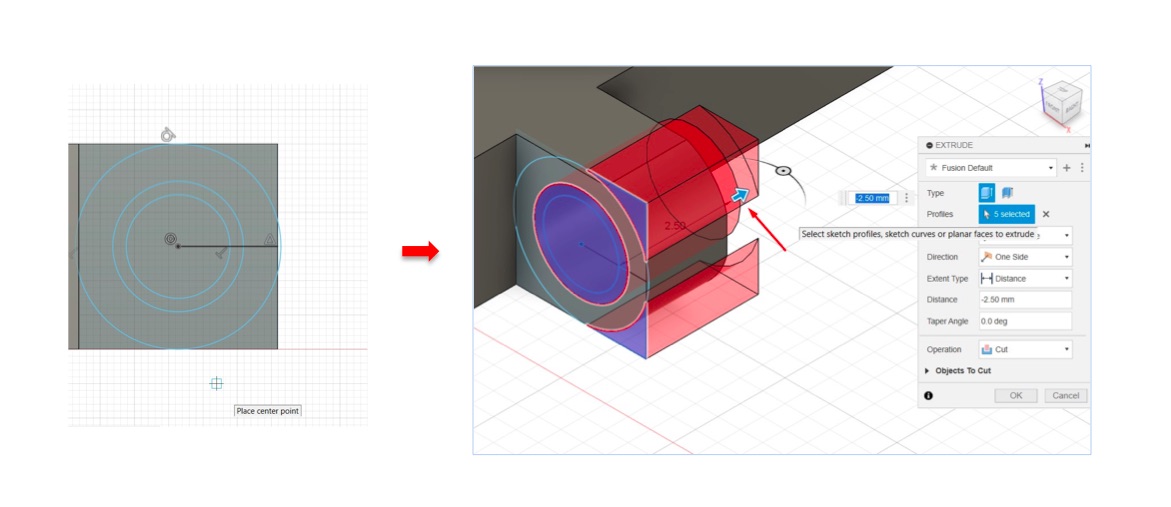
- After that, I selected the small circle to extrude them inside the body using the join option, as shown below.
- I repeated the joint creation process for all segments, ensuring they fit together correctly.
- Here is the final result shape, which I then exported in STL format.